

Fort St. Vrain in Pictures: 3
One of the important design goals for the Fort St. Vrain reactor - really, the second-generation high temperature gas cooled reactor - was to create a core design that would be more compact than that actually used at Peach Bottom. An innovative design was developed using stacked reactor-grade graphite modular blocks which incorporated fuel rods that contained coated fuel particles.
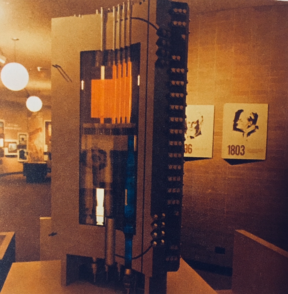 As a reminder, or for those who have not seen the earlier installments, here we see a scale model of the PCRV (Prestressed Concrete Reactor Vessel) and the nuclear steam supply system used at Fort St. Vrain. The active region of the reactor core is at top, in orange, with also-orange control rods aligned vertically through it. The core was surrounded by graphite reflector blocks; the core was roughly 15-1/2 feet tall and 19-1/2 feet across. The graphite reflector surrounding the core was 47 inches thick along the sides, 39 inches thick on the top (above the core) and 47 inches thick below it. (As an aside, the PCRV thickness along the sides, abreast the core, was roughly nine feet.)
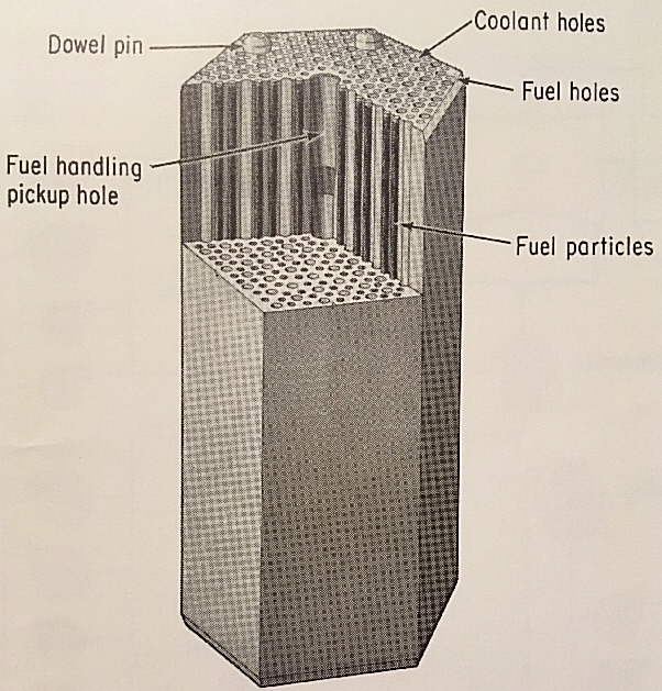
Above is a view of one of the fuel elements. Each of these elements measured about 14 inches wide (from flat to flat) and was 31 inches tall. Inside the structure were tubular openings running vertically; there were 210 to hold fuel, another 100 to allow passage of helium coolant, and in the center a large opening running less than half way down to allow grapple of the element for loading and unloading. Dowel pins aligned the elements stacked on each other to line up coolant passages.
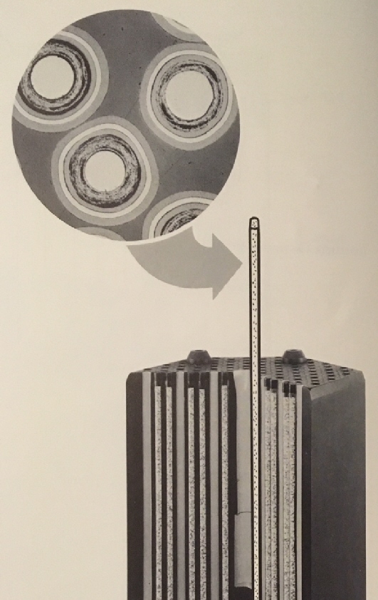
The composite view seen above depicts the fitting of the fuel, contained in rods, into the fuel elements and also displays the structure of the fuel particles. This core contained about 2000 pounds of 93% enriched uranium and, because it was a thorium breeder, about 39000 pounds of thorium 232. As can be seen, fuel rods (each about 0.4 inches in diameter and 15 inches long) were inserted into the graphite elements vertically. Coated fuel particles were dispersed in these rods; the fuel particles were fabricated as described here from materials in the Fort St. Vrain press package:
"The coated fuel particles consist of uranium and thorium dicarbides encased in four separate spherical structures. The layer of coating immediately surrounding the (U, Th) C2 kernel is a porous pyrocarbon structure. This permits expansion of the kernel to occur during fuel life and also provides a porous structure that accomodates the gaseous fission products generated as fuel is consumed. The second coating is a dense, isotropic pyrocarbon that provides the first barrier to the release of fission products. The third coating is silicon carbide, and it performs the function of retaining metallic fission products. The outer coating, a dense isotropic pyrocarbon, is deposited in such a way that it places the silicon carbide coating in compression. Since silicon carbide is a brittle structure, the outer coating prevents it from rupturing due to pressures generated within the particle during its lifetime. These particles are then cast into a .. rod form .. using a carbonaceous binder."
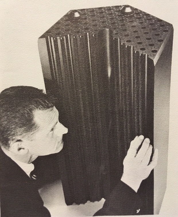 Here we see one of these fuel elements with a person for scale. Each of these elements was rated to produce about 565 KWt at rated continuous power; the core contained 1482 such elements which were not all equally loaded. The core had radial and axial zones of unique fuel load which was intended to flatten temperature across and through the core. According to General Atomic, refueling would occur annually and would see roughly a quarter of the core replaced each time.
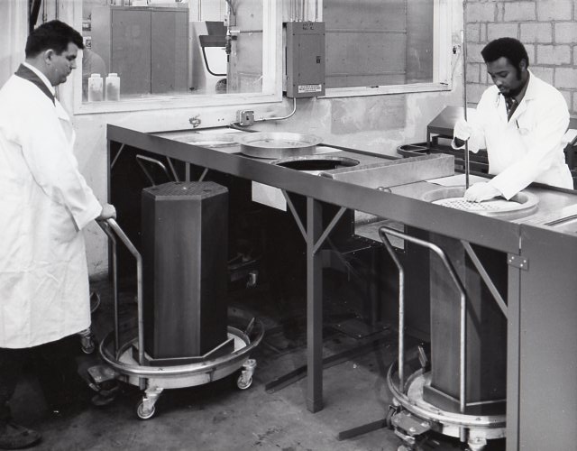 This rare photograph, included in the press package unlabeled, appears to show the manufacture of fuel elements for the Fort St. Vrain reactor at General Atomic. The technician at left is moving a fuel element on a specially constructed cart, perhaps to position it under the work surface; note the rails on the floor to guide the cart to align the fuel element properly underneath the circular table opening. Just visible under the table is a special stop, shaped to hold one flat on an element and parts of two others in order to further ensure alignment of the element during work. The technician at right appears to be installing fuel rods into another graphite fuel element.
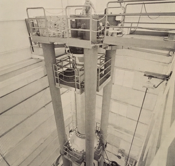
Above we see the specially-designed fuel handling machine for the Fort St. Vrain plant being put through its paces at the headquarters of General Atomic prior to being shipped to the plant for installation.
Coming in future installments: Design and operation of the nuclear steam supply system; fabrication and installation of nuclear steam supply system components; construction of the plant and more!
 Will Davis is a member of the Board of Directors for the N/S Savannah Association, Inc. He is a consultant to the Global America Business Institute, a contributing author for Fuel Cycle Week, and he writes his own popular blog Atomic Power Review. Davis is also a consultant and writer for the American Nuclear Society, and serves on the ANS Communications Committee and the Book Publishing Committee. He is a former U.S. Navy reactor operator and served on SSBN-641, USS Simon Bolivar. His popular Twitter account is @atomicnews.