

Fort St. Vrain in Pictures: 4
We continue this look at original materials covering America's second commercial High Temperature Gas-cooled Reactor (HTGR) with the examination of components of the NSSS, or Nuclear Steam Supply System.
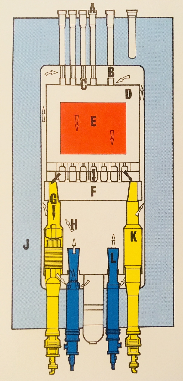
It will be recalled that the Fort St. Vrain plant was equipped with the first prestressed concrete reactor vessel (PCRV) to be employed at a commercial plant in the US, and above we see the components of the NSSS inside the cavity of this vessel. The components are as follows: A. Penetrations for fueling / refueling B. Control rods C. Orifice valves D. Graphite reflector surrounding reactor core on all sides E. Reactor core F. Core support structure G. Flow of hot helium, heated in core H. Flow of 'cold' helium back around core and to its top end where it re-enters core I. is not used.. J. Prestressed Concrete Reactor Vessel K. Steam generator L. Helium circulator.
The flow of helium coolant in the NSSS is fairly obvious from this drawing; what's not obvious is that there was a total of twelve steam generators, piped six each into two loops. There was a total of four helium circulators.
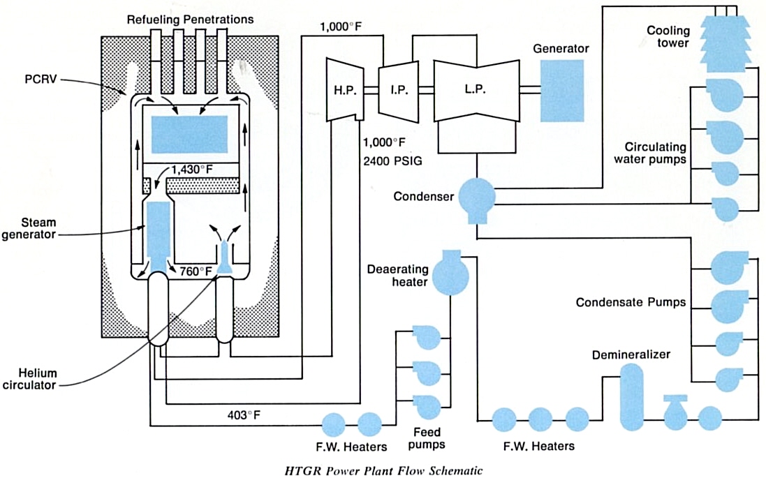 Flow of steam in this plant was more complicated than in others, because the steam was routed back to the NSSS to drive the helium circulators. Steam first left the NSSS from the steam generators at 2400 psig and 1000 F and entered the high pressure turbine, labeled H.P. -- on this diagram it enters the HP turbine at the right. Having driven this turbine, the steam then returned to the PCRV to drive the helium circulators. From the circulators it returned to the steam generators where it was reheated back to 1000 F; it was then routed to the I.P. or intermediate pressure and then the low pressure turbines, driving the generator to power the grid. After being condensed into water, it then flowed to condensate pumps, a demineralizer, a bank of heaters and a deaerating heater, then through the main feed pumps (where it was boosted in pressure in order to be able to enter the steam generators) and finally through another set of heaters before restarting the whole cycle.
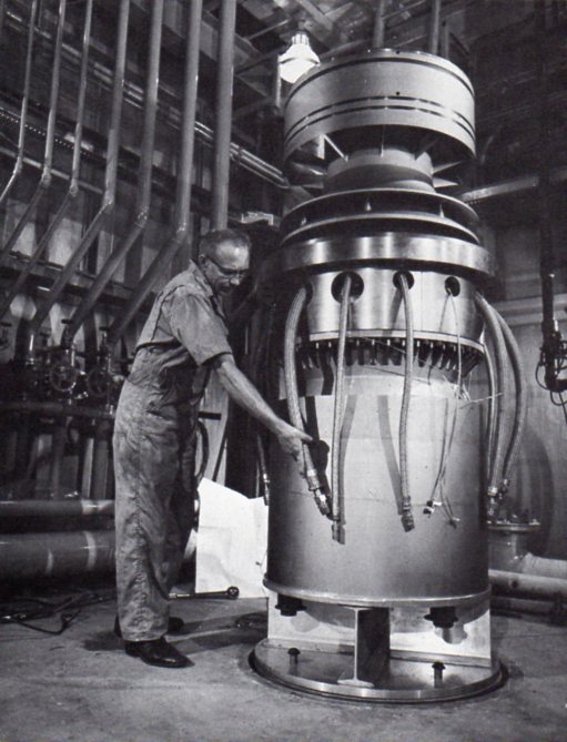
Above we see a prototype helium circulator for Fort St. Vrain being prepared for test by General Atomic. These machines each developed 5500 horsepower (at 9550 RPM) at full steam flow, and were driven by steam at roughly 840 psia and flowing at about 150 lbs. of steam per second. Interestingly these machines could also be driven by steam from other plant sources, and even incorporated a Pelton wheel drive that could be operated by water from the feed, condensate or fire water systems. Operation of the power plant at lower loads caused excess steam supply to these circulators so that a bypass and throttle arrangement was fitted - which also allowed individual control of the circulators if desired.
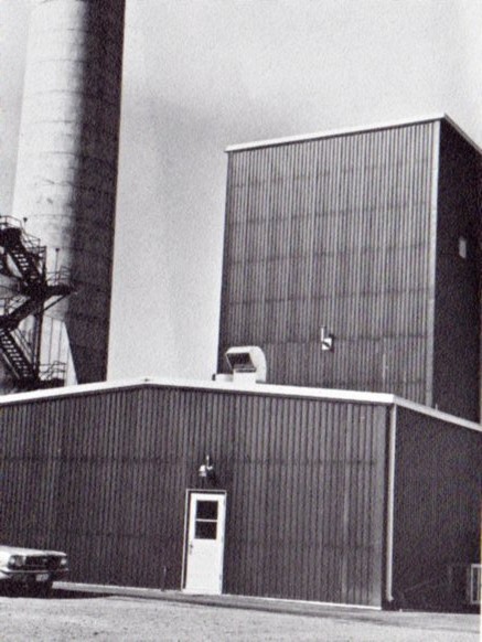
The helium circulator shown earlier was being at Public Service Company's Valmont Generating Station, where General Atomic built the special test facility seen above.
The steam generators employed in this plant were considerably different from those in LWR plants for a variety of reasons; their construction is shown and discussed below.
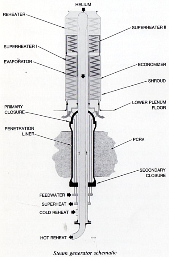 As can be seen above, the flow of helium through the steam generator was fairly simple; in through the top, downward around a variety of tubes and surfaces and then out of the steam generator.
Water first entered the steam generators through the feedwater header connection seen at the bottom, after which the water traveled upward through the economizer (raising water to boiling), evaporator (boiling in bulk), and two superheater sections (raising temperature above saturation temperature). That superheated steam exited through the superheat connection seen again at the bottom. After driving the HP turbine and the helium circulators the steam returned; it entered the cold reheat connection which was concentric with the hot reheat connection that the steam would then exit. The hottest helium from the reactor core first transferred its heat to the reheater; then, less hot, to the superheaters, then further lowering in temperature gave heat to the evaporator and finally at its coolest (but by no means cold) to the economizer. (The core outlet temperature was 1430F; the inlet or helium return temperature was 760F.) In this way the coolant flow and designated heat regions vaguely parallel those found in the once-through steam generators used in Babcock & Wilcox PWR nuclear plants - and of course, these Fort St. Vrain steam generators were also technically once-through and not recirculating types.
Particularly interesting was the insertion of the relatively large, insulating penetration liner and secondary closure which was intended to shield the PCRV from excessive heat and provide containment. The steam generators were essentially mounted on top of these.
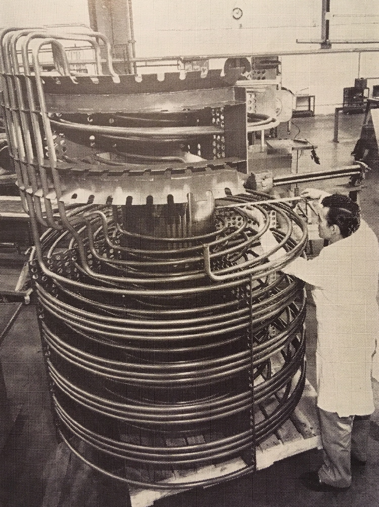
This General Atomic photo shows the construction of a mockup for the Fort St. Vrain steam generators. Obvious is the helical coil design of the tubes for carrying water and steam.
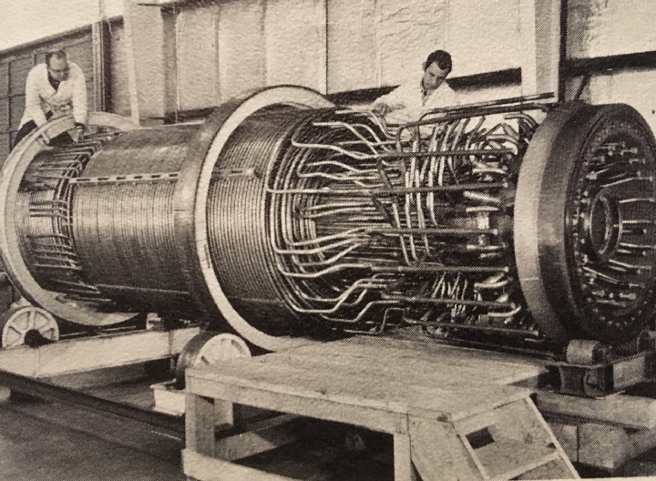
General Atomic photo showing one of the twelve steam generators for the Fort St. Vrain plant in advanced stage of fabrication.
The Valmont helium circulator test facility seen earlier was not the only special test facility built to prove out HTGR concepts prior to construction, as is shown by the following illustration of a test rig built to prove out the core and vessel of the prior design for the Peach Bottom Atomic Power Station. It was included in the original Fort St. Vrain press package and is reproduced here for interest.
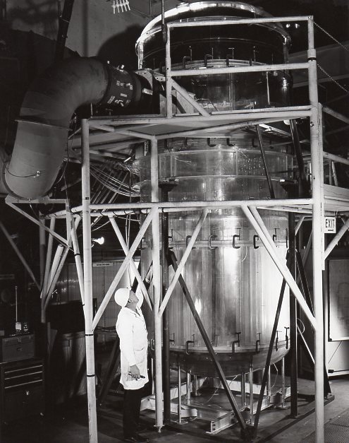 (Above.) "Engineers at General Atomic Division of General Dynamics Corporation in San Diego are using this transparent half-size scale model of the High Temperature Gas-cooled Reactor to Simulate the helium gas flow conditions through the HTGR core and pressure vessel. This five-ton model duplicates in every detail but in miniature the internal helium-coolant flow paths of the HTGR and includes half-size dummy aluminum fuel elements. The horn-shaped air intake is seen at top left."

Peach Bottom Atomic Power Station (author's files.)
In a very real way, construction of the Fort St. Vrain Nuclear Generating Station hinged upon success of the first commercial HTGR at Peach Bottom. That plant, given a construction permit in 1962 and first started up in March 1966, was immediately put through its paces while Public Service of Colorado waited to see the results. From a PSCo brochure in the Fort St. Vrain press package:
Final go-ahead on Fort St. Vrain also was contingent upon the successful completion of a nine-month review period of full power operation of the Peach Bottom Atomic Power Station. The Pennsylvania plant entered this review period in June of 1967. Upon completion of 1000 hours of operation early in the nine-month period, the Director of the AEC's Division of Reactor Development and Technology stated "It is a significant event for Peach Bottom, which is a vital part of the HTGR program."
Approvals for the Fort St. Vrain plant from authorities were received in 1968. The AEC's Atomic Safety and Licensing Board authorized a construction permit for Fort St. Vrain on September 16, 1968 and this was issued by the AEC two days later. Earlier that year, PSCo had obtained a "Certificate of Convenience and Necessity" from the State of Colorado Public Utilities Commission. Construction of the plant began immediately after issuance of the AEC construction permit.
Next installment: Construction of the Fort St. Vrain Nuclear Generating Station. Illustrations used in this series are, unless noted, from a press package covering the Fort St. Vrain Nuclear Generating Station in the author's collection.
 Will Davis is a member of the Board of Directors for the N/S Savannah Association, Inc. He is a consultant to the Global America Business Institute, a contributing author for Fuel Cycle Week, and he writes his own popular blog Atomic Power Review. Davis is also a consultant and writer for the American Nuclear Society, and serves on the ANS Communications Committee and the Book Publishing Committee. He is a former U.S. Navy reactor operator and served on SSBN-641, USS Simon Bolivar. His popular Twitter account is @atomicnews
Feel free to leave a constructive remark or question for the author in the comment section below.